
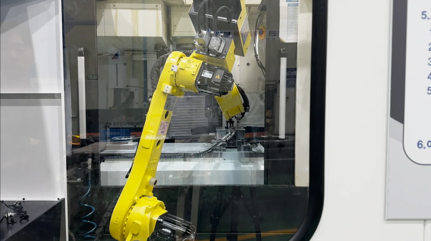
Automating CNC machine loading and unloading is not a matter of placing a robot beside a machine and teaching two positions. A production-ready cell must control the complete loop: present a known raw part, grip it consistently, confirm the CNC is ready, open the door, exchange the part, start the cycle, manage finished parts and recover safely from faults. This guide explains that loop in the order a shop should engineer it. It also shows where projects usually fail, which inputs an integrator needs, and how to move from a promising demonstration to a repeatable production process.
01Define the production problem before choosing a robot
Begin with the production constraint, not the robot brand. Document the current loading sequence from the last good finished part to the first good part of the next cycle. Record how the operator identifies raw parts, orients them, opens the CNC, cleans the fixture, seats the part, confirms clamping, starts the cycle and handles the completed part. The result is a real process map rather than an assumption.
The minimum application data includes part dimensions and weight, raw and finished geometry, material, machining cycle time, shift pattern, batch size, changeover frequency, chuck or fixture type, available machine signals, floor space and the unattended production target. The complete guide to CNC machine tending automation provides broader context for deciding whether the process is repeatable enough to automate.
A strong requirement is measurable. Instead of saying that the shop wants more output, define a target such as maintaining part exchange below a chosen time, running through breaks, or completing a specific number of pieces after the last staffed shift. Those targets determine how much part capacity, fault recovery and verification the cell needs.
- Capture the real cycle, including door motion, chuck motion, air blow, gauging and operator checks.
- Separate machining time from manual load and unload time so the automation opportunity is visible.
- List every part variation that the same cell must handle during the first implementation phase.
- Define acceptance criteria before the equipment is selected.
02Choose how raw and finished parts will flow
Part presentation determines unattended capacity, changeover work and floor-space use. Common approaches include fixed trays, drawers, turntables, carts and vision-guided bins. Fixed-location presentation is normally the simplest to validate because each part has a known pickup position. Random bin picking can add flexibility, but it also adds vision, collision and part-separation variables that may not be justified for a first cell.
Capacity should be calculated from the production target. If the machining cycle is eight minutes and the goal is four unattended hours, the system needs space for at least 30 raw parts and 30 finished parts, plus a practical buffer. Heavy or large parts may reduce that count and shift the best solution toward a cart, turntable or custom rack. Small parts may fit efficiently in a drawer system.
YC Robotech offers several loading architectures across the Labot system range. The right choice depends on part size, part weight, autonomy target, machine count and available floor space. A system with the highest nominal capacity is not automatically the best. The best system is the one operators can reload and change over without creating a new bottleneck.
As a starting point, the Labot SD loads smaller parts from drawers with removable pallet trays in a compact collaborative cell. The Labot MD loads larger parts in similar drawers when one robot needs to serve two CNCs. The Labot MT loads from a split turntable, so operators can restock one side while the robot works from the other. The Labot SQ loads from a mobile cart that is filled away from the machine and rolled into the cell. Final selection is always confirmed during application review.
Design for two material states
Raw and finished parts must remain distinguishable. Dedicated locations, status tracking or a controlled transfer sequence prevents a finished part from being loaded again and prevents an empty location from being treated as a valid pickup.
Include chips and coolant in the design
Finished parts can carry coolant and chips back to the presentation system. Drainage, part orientation, air blow and easy cleaning are production requirements, not cosmetic details.
03Select the robot, reach and end-of-arm tooling
Robot selection begins with payload at the wrist, not part weight alone. The calculation must include the gripper, fingers, adapters, sensors, hoses and the heaviest part. Reach must cover pickup, load, unload, cleaning and reject positions without operating continuously at the edge of the robot envelope. The cell layout should also preserve service access to the CNC and a safe recovery position.
End-of-arm tooling is where repeatability becomes physical. A dual gripper can remove a finished part and load a raw part in one door-open event, reducing exchange time. A single gripper can be simpler and lighter. Part geometry may require external gripping, internal gripping, magnetic handling or custom fingers. Whatever the method, the design needs positive grip confirmation and a defined response when confirmation is missing.
Do not design fingers only from the finished drawing. Raw stock variation, burrs, saw-cut length, casting variation, oil and chips can change how the part seats. Test with representative production parts. If multiple families are planned, quantify what changes: fingers, gripper, tray, robot recipe, CNC program, fixture, or all of them.
04Engineer the CNC interface and sequence
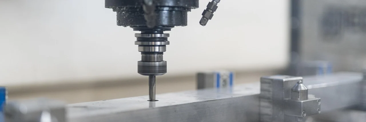
The robot and CNC need a controlled handshake. Typical signals include machine ready, cycle complete, door open, door closed, chuck open, chuck closed, robot clear, cycle start and fault status. The exact method depends on the CNC control, available I/O, door automation, chuck or fixture controls and the machine builder requirements. This is why compatibility must be checked against the actual make, model, control and options.
The sequence should never depend only on elapsed time. Waiting five seconds and assuming a chuck is open is weaker than receiving a confirmed chuck-open signal. A robust sequence verifies each safety-critical or process-critical state before continuing. It also defines timeouts and tells the operator what failed in useful language.
The CNC robot integration capability page explains the role of machine communication and integration. The Smart EZ software supports a guided six-step setup for compatible Labot applications: select the model, select the pallet/tray type, set the recipe, configure the model, set the workpiece position and apply it to the CNC, all without writing robot code.
- Confirm who supplies the automatic door interface and whether the machine builder must approve modifications.
- Verify chuck, fixture and clamp feedback rather than assuming a command succeeded.
- Define robot-clear and machine-safe positions before allowing cycle start.
- Provide actionable fault messages and a documented recovery sequence.
05Complete the risk assessment and safeguarding design
Safety is a cell-level engineering task. A collaborative robot does not make an entire application collaborative by itself. The workpiece, gripper, sharp edges, hot parts, CNC motion and stored pneumatic energy can all introduce hazards. The safeguarding method must follow a documented risk assessment for the installed application and the way people will operate, clean, recover and maintain it.
In the United States, OSHA 29 CFR 1910.212 requires one or more guarding methods to protect employees from machine hazards, including point-of-operation hazards, rotating parts, flying chips and sparks. Servicing and maintenance can also fall under OSHA 29 CFR 1910.147, which addresses control of hazardous energy. Current industrial robot safety requirements are covered by ANSI/A3 R15.06-2025, with Parts 1 and 2 addressing industrial robots and robot applications or cells.
Depending on the assessment, the solution may use fencing and interlocked access, safety scanners, light curtains, safe speed and separation monitoring, or a combination. Validation must confirm stopping performance, safety functions, access control and restart behavior. The machine owner remains responsible for the safety of the installed system and operating practices.
06Build, test and prove the complete production loop
Factory acceptance testing should use representative parts, programs, tooling and process conditions. A clean demonstration with one ideal part does not prove production readiness. Test the full loop for enough cycles to expose accumulated variation, coolant behavior, chip buildup, gripping drift and operator recovery issues. Include a deliberate fault list: missing part, double part, misloaded part, dropped part, full finished tray, machine alarm, door timeout, chuck confirmation failure and loss of air pressure.
Measure the results against the acceptance criteria defined in Step 1. Relevant measures include part-exchange time, successful cycles without intervention, good-part count, changeover duration, alarm frequency and operator recovery time. If automatic gauging, part marking or washing is in scope, validate those operations in the same run.
Site acceptance adds the real environment: actual utilities, network, floor conditions, machine condition, shift staffing and material flow. Train operators on normal production, changeover and basic recovery. Train maintenance personnel on safe isolation, diagnostics and approved adjustments. Provide backups for robot programs, recipes, safety configuration and interface documentation.
07Launch with a controlled ramp and improve from evidence
Start production with a defined ramp instead of declaring success after installation. Track why the cell stops and separate robot faults from upstream CNC alarms, material shortages, chip problems, tool-life events and quality holds. That distinction prevents the robot from becoming the default explanation for every lost minute.
Review the first weeks with operators and maintenance. Small changes to finger geometry, air-blow timing, part orientation, alarm text or replenishment work can remove repeated interruptions. Freeze a stable baseline before adding more part families or unattended hours. Once the cell is capable and the team trusts recovery, expand deliberately.
A successful CNC loading project is a production system, not a robot purchase. When part flow, tooling, interface, safety, validation and operator ownership are engineered together, automation can keep the spindle supplied without requiring a person to repeat the same door-and-chuck cycle all shift.
08Implementation checklist
Use this checklist before requesting a firm automation proposal. It keeps the discussion tied to the real application and exposes missing scope before it becomes a change order.
- Part drawing, sample raw part and sample finished part are available.
- CNC make, model, control, serial number and interface options are documented.
- Fixture or chuck commands and confirmations are understood.
- Machining time, manual exchange time, batch size and target unattended hours are measured.
- Required part capacity, raw-to-finished flow and reject handling are defined.
- Robot payload, reach, gripper concept and changeover needs are verified.
- Risk assessment ownership, guarding concept and validation scope are assigned.
- Acceptance test, training, documentation and production ramp criteria are written.